ISO 13849-1:2023 and Performance Level (PL) Requirements for Corner Crimping Machine Safety
Core Architecture Rules for Safety-Related Parts of Control Systems (SRP/CS)
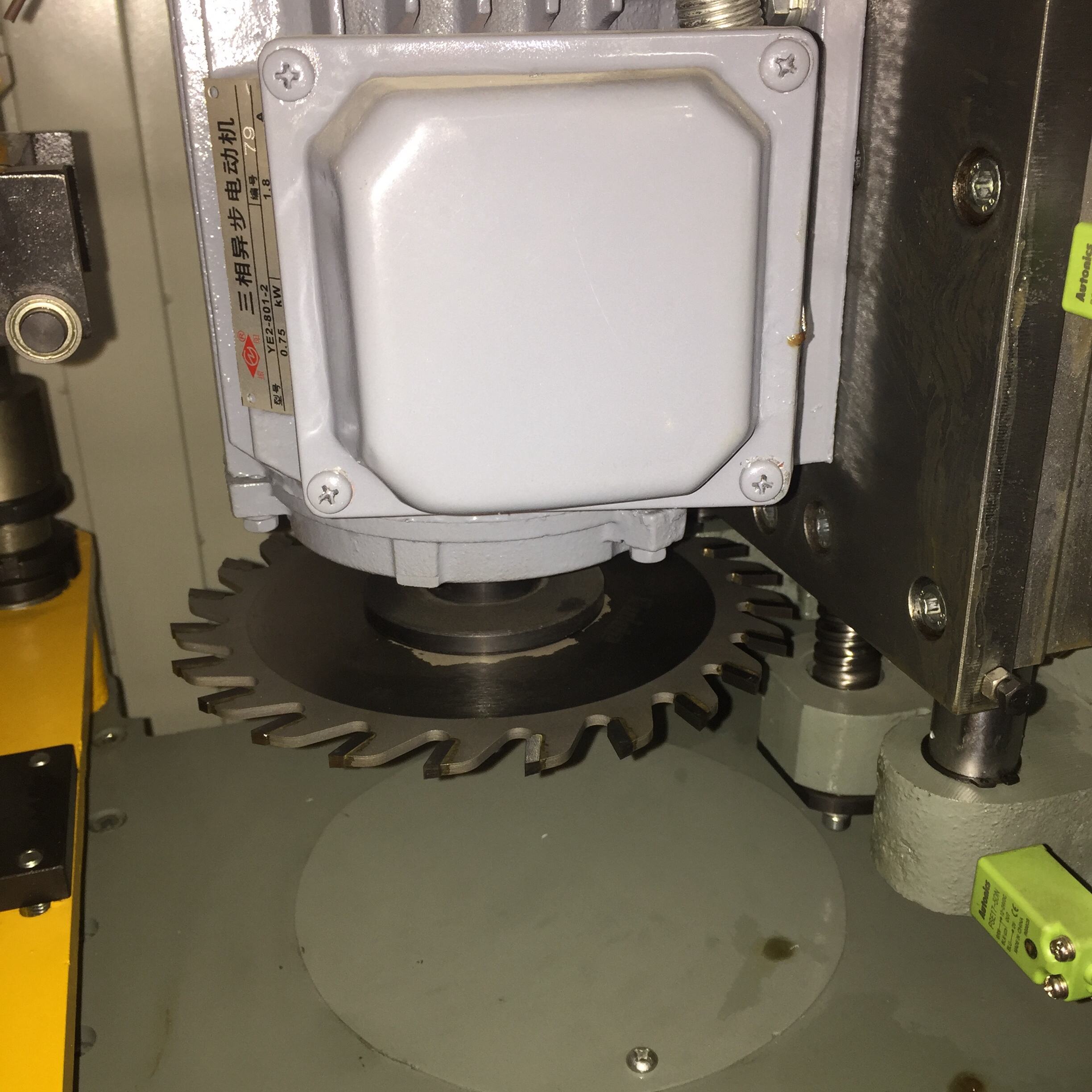
The ISO 13849-1:2023 standard sets out specific requirements for Safety-Related Parts of Control Systems (SRP/CS), grouping them into different categories from B through to 4 depending on how well they handle faults and what kind of diagnostics they offer. When it comes to corner crimping machines where the hydraulic force can easily go over 500 kN, most installations need to meet Category 3 standards. What does this actually mean? Well, systems have to include backup safety pathways, run ongoing checks on their own performance, and maintain at least a 100 year MTTFD rating for PLd performance level. The diagnostic coverage also needs to be above 90%, so any problems with essential safety equipment such as light curtains or emergency stop buttons get picked up almost instantly. This matters because dangerous restarts happen all too often when changing tools, and these incidents remain one of the main causes of serious crush injuries in manufacturing settings.
Determining Required Performance Level (PLr) from Risk Assessment Data
The required Performance Level (PLr) is derived directly from risk assessment data per ISO 12100. For corner crimping machines, typical hazard parameters include:
- Severity (S): Catastrophic (S2), due to high probability of amputation under multi-ton forces
- Exposure Frequency (F): Continuous (F2) in auto-fed production lines
- Avoidance Probability (P): Low (P2), given limited operator reaction time near the point-of-operation
- Hazard Occurrence Probability (O): High (O3), driven by frequent material jams
For critical safety features like two hand controls or light curtain protection, we typically see these values landing at PLr equals d or e. Take PLr equals e as an example it demands components where the MTTFD is at least 30 years and the DC hits 99% or better, all checked against standards from ISO 13849-2. Get this right in practice and there's a real drop in accidents, maybe around 98% fewer incidents than what happens with PLc systems during automated crimping operations. Of course, getting those numbers isn't just about math it's about making sure everything works together properly on the factory floor.
Risk Assessment Fundamentals per ISO 12100: Identifying Corner Crimping Machine Hazards
Quantifying Severity, Frequency, and Avoidance Probability in High-Force Crimping Operations
ISO 12100 mandates a systematic, evidence-based approach to quantifying three core risk parameters. In corner crimping:
- Severity reflects worst-case injury outcomes—crushing forces above 100 kN commonly meet S2 (“severe”) criteria due to permanent musculoskeletal damage or amputation.
- Exposure frequency depends on operational mode: F2 (“continuous”) applies to fully automated feeding; F1 (“frequent”) may apply where manual loading occurs several times per shift.
- Avoidance probability is rated P2 (“low”) when tool closure speeds exceed 0.5 m/s—leaving insufficient time for evasive action.
Accurate quantification requires documenting worst-case injury scenarios, measuring hazard duration across full crimp cycles, and verifying spatial constraints for operator retreat. This objective foundation ensures residual risk aligns with ALARP (As Low As Reasonably Practicable) principles.
Translating Hazard Scenarios into Specific Safety Functions (e.g., Safe Stop Category 1)
Hazards identified through ISO 12100 feed directly into technical safety specifications via its iterative risk-reduction framework. For example:
- Uncontrolled tool closure during maintenance — Safe Stop Category 1, requiring monitored electro-mechanical braking (<150 ms halt time) plus position verification.
- Crushing hazards from residual tool inertia — Safe Torque Off (STO) with directional motion monitoring.
- Repetitive material loading — Light curtain integration with ≤30 mm resolution and muting logic compliant with ISO 13855.
- Stuck component interventions — Three-position enabling switches, physically preventing activation unless held in the “enable” position.
Each function must be sized and validated to match the original hazard’s severity, frequency, and avoidance profile—ensuring safety controls target precise failure modes without over-engineering.
Safe Integration of Protective Devices in Automatic Corner Crimping Control Systems
Selecting and Validating Light Curtains, Interlocked Guards, and Enabling Devices
Protective device selection must comply with ISO 13849-1:2023 architectural rules and performance targets. For high-force corner crimping:
- Light curtains require ≤14 mm resolution for finger detection and must achieve at least PLd, verified through Type 4 design validation (IEC 61496-1).
- Interlocked guards demand dual-channel magnetic switches with cross-monitoring to prevent defeat, coupled with forced-guided contacts meeting Category 3 architecture.
- Enabling devices must incorporate spring-return mechanisms that require continuous pressure and fail-safe release.
All devices undergo fault-injection testing to confirm diagnostic coverage >90%. Perimeter guarding must withstand 200 J impact energy (per ISO 14120) and support <100 ms emergency stop response (ISO 13850). Environmental validation—including vibration resistance up to 15g and IP65 sealing against metal particulate ingress—is mandatory for reliable operation in industrial crimping environments.
Stop Categories, Restart Logic, and Response Time Validation for Dynamic Crimping Cycles
Stop categories must match the dynamic nature of crimping operations. Category 0 (uncontrolled power removal) applies to imminent collision hazards, while Category 1 (controlled stop followed by power removal) is required for inertial hazards requiring deceleration control. Restart logic must enforce dual-hand consent with asynchronous actuation detection to eliminate accidental reactivation.
When validating response times, we need to consider all those little delays that add up over time. Think about things like light curtain processing which takes around 10 milliseconds or less, then there's the safety PLC scan cycle at about 15 ms max, and finally the contactor opening itself usually under 20 ms. In situations involving high speed crimping operations, manufacturers need to show that their entire safety function works within a 50 millisecond window when measured with an oscilloscope. Why does this matter? Well, according to standard EN ISO 13855:2019, the safety distance calculation formula S equals K multiplied by T plus C becomes critical here. For manual access points, K stands for 1600 mm per second. Getting these numbers right means operators stay safe even during those fast repetitive cycles that happen throughout production runs.
FAQs
What is the ISO 13849-1:2023 standard?
ISO 13849-1:2023 sets requirements for Safety-Related Parts of Control Systems, helping ensure machinery like corner crimping machines meets specific safety standards.
Why is diagnostic coverage important for safety equipment?
High diagnostic coverage ensures any malfunctioning safety equipment, like emergency stop buttons, is detected swiftly, preventing dangerous machine restarts which can cause serious injuries.
How is the Required Performance Level determined?
The Required Performance Level (PLr) is determined through risk assessments, where factors like severity, exposure frequency, and avoidance probability are evaluated.
What are critical safety features for corner crimping machines?
Critical safety features can include two-hand controls, light curtain protection, and stop categories, all designed to reduce accidents significantly.